
Upgrades and 'improvements'
Lights on warning buzzer
Disclaimer The TVR Car Club will not accept responsibility for any damage caused to any vehicle as a result of using this information.
Reproduced with kind permission of Andy Field
This device will emit a steady 'beep' if you have inadvertently left your lights on. The logic of the circuit is such that the 'beep' will only sound if the ignition is switched off (key position '0' or 'B'), the lights are switched on and either door is open. It has been fitted to a 1999 Chimaera 450, but fitment should be the same for other models.
Parts used

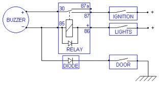
A standard 12V relay (having terminals '30', '87', '85' and '86'). In my project I used a Hella 4RD 003 520-25 (only because I bought several in a job lot from eBay). This also has an '87a' terminal, not used in this installation. The contacts are rated at 25A, but as the circuit uses only a tiny current, any 12V relay would suffice.

A 12V piezo buzzer - I used an LS00635 (available at www.cpc.co.uk). It has a frequency of 5.2kHz, volume of 90dB but only draws a current of 8mA. As it is quite loud I muted it with a piece of insulating tape.
|
Wire - As the current requirement is very small, almost any wire can be used, but I'd recommend something in the range of S.W.G. 20 to 30. I actually used an old computer power lead, stripped down, to give me three 2m lengths of wire in three different colours.
|

'Lucar' connectors - Red or blue crimp connectors are the easiest to use, although I used bare connectors and soldered the wires to them. They were then fully insulated using shrink tube. For this project I used red shrink tube for the 'live' connections and black shrink tube for the 'ground' connections (again because I bought a job lot of shrink tube from eBay). This gives the job a more professional finish. Shrink tube needs to be shrunk using a heat gun, but if you don't have one, careful use of a lighter will suffice.
|
Loom tape - Again, for a more professional look, I bound the finished wiring loom in loom tape (also from eBay), although you could use normal insulating tape.
|

Fuse holder - Various types of fuse holder are available; the easiest to use is an in-line holder. The best type to use is a blade fuse holder, with Lucar connections, but I had a different one lying around, with soldered connections, so I used that instead.

Velcro - In true TVR fashion, the relay and the buzzer were both mounted using Velcro! The buzzer was mounted in the bottom section of the cowling around the ignition switch. The relay was mounted on to the bottom surface of the dashboard panel, just above the steering column. Note the back edge of the ignition switch cowling, just visible at the top of the photograph (taken looking upwards from the footwell).

Diode - As the door switch circuit is also used by the alarm and central-locking systems, a diode is required in this part of the circuit to prevent a possible unwanted interaction between those circuits and the lighting circuit. I used a 1N4001 (from www.cpc.co.uk) which is commonly available from other sources.
Circuit logic
Circuit logic
The Chimaera uses a steering column from a Vauxhall Cavalier (1988-1995), along with its ignition switch, indicator/main beam switch and washer/wiper switch. The ignition switch has a spare terminal (used to feed the Cavalier radio, unused by TVR). This terminal is 'live' when the ignition switch is off. By using this terminal we have the advantage of a 'lights on' reminder whose relay is only energised if the lights are on and the door open, instead of a system whose relay is always energised when the ignition is switched on.
The dashboard top had been removed (for re-veneering the front panel), so I took advantage of this to make the connections to the lighting circuit and door switch under the dashboard. Otherwise, the feed to the dashboard light switch, the pointless one that your left knee switches off, can be used to pick up a 'live' connection from the lighting circuit.
I spliced the connection to the door switch circuit where it exits the back of the dashboard en route to the main fusebox. Carefully, I cut the loom tape back and found the door switch wire: in my car it is white with a purple stripe. I identified it by using a multimeter to measure the voltage between it and 'ground'. It should be at battery voltage (in this case a healthy 13.6V) with the doors closed, falling to 0V with a door open. Alternatively you could route the cable along the inside of the sill and make the connection at the door switch itself.
Installation
Decide where to mount the relay and piezo buzzer and identify the location of each connection you will be making. Run the necessary wires from point to point, cutting them to length as you go. Use a small piece of insulating tape to hold the wires together. Where wires need joining together, eg. between the buzzer and your new loom, the best way to do this is to twist them together, solder them, then insulate the connection preferably with shrink tube, but you could also use insulating tape. The wire from relay terminal '85' needs to be joined to the negative wire from the buzzer. This can be done by soldering both to the 1N4001 diode's leg (the leg opposite the silver band painted on the diode's body). The wire to the door switch can then be soldered to the diode's other leg (nearest the silver band) and the whole lot insulated with shrink tubing or insulating tape. Now bare the wire ends and fit the Lucar connectors. Make all the necessary connections, stick Velcro in the chosen locations and on the buzzer and relay and test.
If the device is working properly, wrap the loom tape tightly around the finished bundle of wires. The loom tape is not adhesive, so the loose end will need to be secured with insulating tape.