
Upgrades and 'improvements'
Manual engine fan override
Disclaimer The TVR Car Club will not accept responsibility for any damage caused to any vehicle as a result of using this information.
Reproduced with kind permission of Andy Field
'Otter switch' failure can result in the engine cooling fans not operating, particularly on models where the switch is mounted in the swirl pot, where it can receive unwanted heat from the exhaust manifold. In the case of such a failure, the switch can be bypassed by linking its supply wires together with a paper clip, an effective method to 'get you home', but this leaves the fans switched on permanently.This device is simply a switch to enable manual operation of the fans. It is often achieved by reusing the switch originally used to turn off the dashboard lamps, but as I had already reused this switch for another purpose, I took a slightly unconventional approach: I used the rear wiper switch. As far as I am aware TVR never fitted a rear wiper, so your car won't have a rear wiper switch! But a plug-in replacement is available, as the switchgear was sourced from a Vauxhall Cavalier (1988 to 1995). The same switch is still in use on at least one current Vauxhall model, the Corsa.
Others who have fitted a manual fan override switch have also fitted an indicator to show the fans have been switched on manually. This is often an LED mounted on top of the steering column cowling. But in this project, fitted to a 1999 Chimaera 450, I used the red warning lamp in the bottom of the tachometer. The same tachometer is used in the Cerbera and this warning lamp is there (I believe) to indicate it's time to change gear. It is not used in the Chimaera, but the lamp and its wiring are present.
Parts used

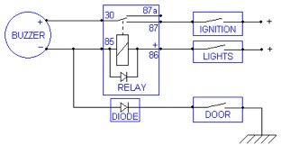
A standard 12V relay - A standard 12V relay (having terminals '30', '87', '85' and '86'). In my project I used a Hella 4RD 003 520-25 (only because I bought several in a job lot from eBay). This also has an '87a' terminal, not used in this installation. The contacts are rated at 25A, but as the circuit uses only a tiny current to drive the fan relays, any 12V relay would suffice.
|
Wire - As the current requirement is very small, almost any wire can be used, but I'd recommend something in the range of S.W.G. 20 to 30. I actually used an old computer power lead, stripped down, to give me three 2m lengths of wire in three different colours.
|

'Lucar' connectors - Red or blue crimp connectors are the easiest to use, although I used bare connectors and soldered the wires to them. They were then fully insulated using shrink tube. For this project I used red shrink tube for the 'live' connections and black shrink tube for the 'ground' connections (again because I bought a job lot of shrink tube from eBay). This gives the job a more professional finish. Shrink tube needs to be shrunk using a heat gun, but if you don't have one, careful use of a lighter will suffice.
|
Loom tape - Again, for a more professional look, I bound the finished wiring loom in loom tape (also from eBay), although you could use normal insulating tape.
|
|
Velcro - In true TVR fashion, the relay was mounted using Velcro, on to the bottom surface of the dashboard panel, just above the steering column. Note the back edge of the ignition switch cowling, just visible at the top of the photograph (taken looking upwards from the footwell).
|

Cavalier wiper switch with rear wash/wipe - This was bought from a breaker's yard, as a length of the attached wiring is also needed. The photograph shows the back of the original switch. You will note that the new switch has an extra terminal '53H'. This is the terminal we need to use.
Circuit logic
Circuit logic
The otter switch works by grounding a supply line. As the Cavalier switch provides a +12V supply, we need to use a relay. This enables the +12V from the '53H' terminal on the wiper switch to ground the otter switch supply line.
The dashboard top had been removed (for re-veneering the front panel), so I took advantage of this to make the connection to the otter switch under the dashboard. Otherwise, you could run a wire to the engine bay and make the connection at the otter switch itself. I spliced the connection to the door switch circuit where it exits the back of the dashboard en route to the main fusebox. Carefully, I cut the loom tape back and found the otter switch wire: it is green with a white stripe. I identified it by using a multimeter to measure the voltage between it and 'ground'. It should be at battery voltage (in this case a healthy 13.6V) with the fans off, falling to 0V with them running. Of course, it was necessary to run the engine up to temperature to check this, but you could simulate the same effect by shorting the otter switch wires together. In this particular project I found two other green/white wires in the loom before I found the right one, so beware!
Installation
Remove the steering column cowling. The two halves are screwed together on the front face (the screws may be covered by small plastic plugs). This will free the top half. The bottom half is secured from underneath by three screws.
Unclip the connector from the wiper switch and unclip the wiper switch from its mounting. Take the connector that came from the breaker's yard apart to free the '53H' terminal wire. Locate and unfurl the wires from the red indicator lamp in the tachometer.
Decide where to mount the relay and identify the location of each connection you will be making. Run the necessary wires from point to point, cutting them to length as you go. Use small pieces of insulating tape to hold the wires together. Where wires need joining together, eg. between the tachometer warning lamp and your new loom, the best way to do this is to twist them together, solder them, then insulate the connection preferably with shrink tube, but you could also use insulating tape. Now bare the wire ends and fit the Lucar connectors. Your new '53H' connector can be pushed into your existing wiper switch wiring connector. The 'ground' connections can be made at the same point as the horn 'ground' connector, a screw on the left hand side of the steering column boss assembly. Make all the other necessary connections, stick Velcro on the relay and its chosen mounting location and test.
If the device is working properly, wrap the loom tape tightly around the finished bundle of wires. The loom tape is not adhesive, so the loose end will need to be secured with insulating tape. Refit the cowling: job done!